
Since I messed up then repaired the one front main rod I have ordered my drivers and wait not very patiently for them before getting into the main rod assembly. In the mean time I have finished up the valve gear assembly, the cylinder cock assembly, and the main drive rod and crosshead. I also completed the cow catcher, which I largely didn’t photograph for some reason. Everything was then taken apart and painted.
The Cow Catcher:
This was an interesting project. Thankfully I have a photo that gives me lots of detail. Why was it interesting? Well the drawings I had led me astray. Since I had this photo I could work with my drawings and come up with something that I think is correct.


Sounds easy eh? Yeah not so much. The above photo shows the first iteration. this was too wide. Again this was figured out by luckily having the General Arrangement drawing (which does not show the cow catcher), David Fletcher’s plans, the plans I had from SL&NGG, and the top photo. So I drew another one and started over. Oh and the wood? Pine strips cut on a table saw.
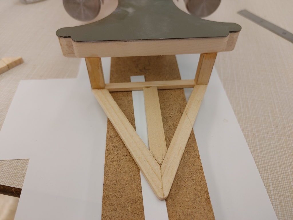
Once I got this done, the frame hanging out there was just waiting to be broken off, so I quickly figured out the spacing and thickness of the boards based on the photo and started quickly building them. I guess I was in a hurry to ensure this was solid so I never took in process pictures.

Main Rods
Since the connecting rods are going to have to wait for the drivers to show up, I set about working on the main rods.

The bits have all been laser cut. The cross head has a plastic cover over it for the detail, but it is steel with a brass insert for the cross head guide bearing. Of course, part of the fun is putting the pieces together and running it to see if it runs smooth. In the original state in the above picture when I put the assembly together and turned it over by hand (I removed one gear from the gearbox) I found that the cross head travel was too far back on the guide. I took it apart and ended up making steel pieces instead of the plastic shown in the above photo, and moved the pivot hole forward….too far. Take it apart again and move the pivot holes back about half way in between the first and second attempts. The video below is the first assembled test.
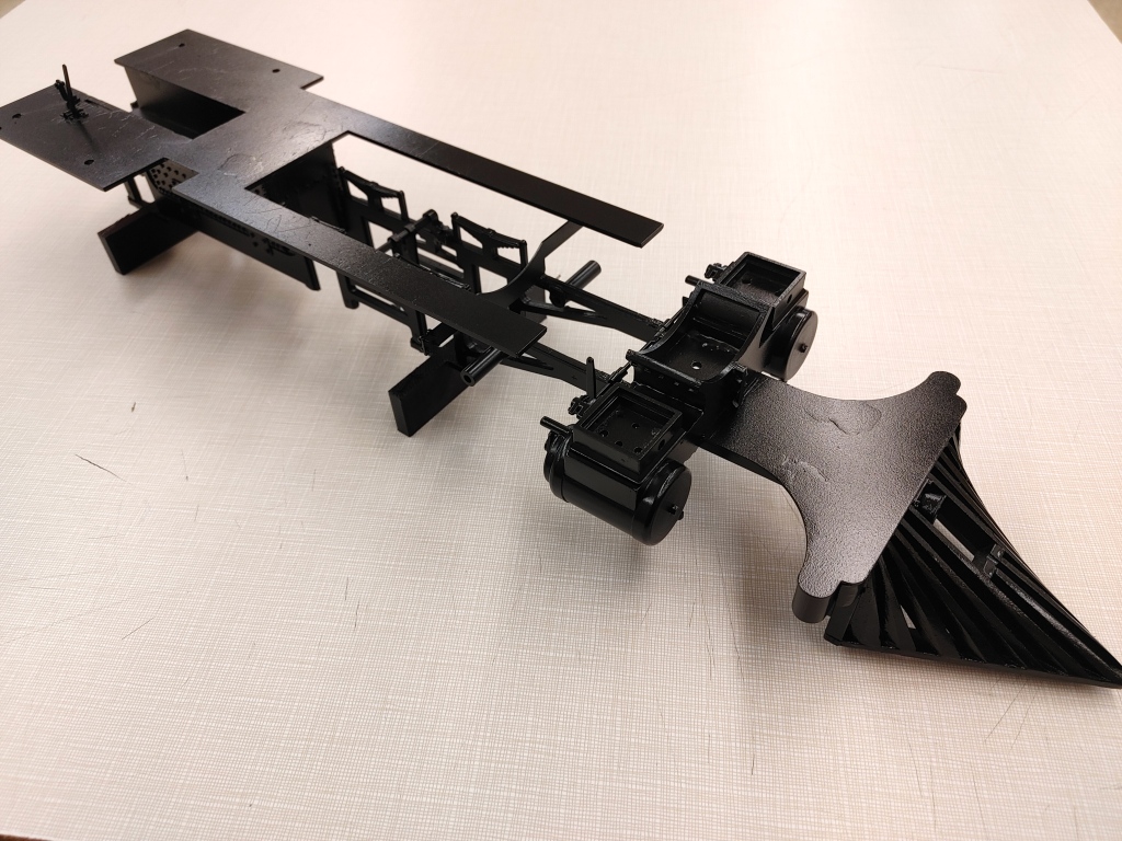
Painting
Once everything is tested and shown to be functioning properly it has to come apart for painting. For it’s day this loco was a bit of a rarity in that it was painted black. The D&RG ordered it that way. If it wasn’t specified it would have been a dark green. Sure makes it easier to get paint when it’s black. The correct Baldwin green colour is RAL 6008 “olive Green”. If it had been this colour I would have ordered from myperfectcolor.com. It’s not cheap, but they will custom mix any colour and put it in a spray can.
Once I finished the testing I thought i would like to see what the loco looks like with all the parts just sitting in place. A bit of self motivation. A project like this is a loooonnnnnggg slog. Sure I enjoy the process, but there are times when you look at what is sitting in front of you and you realize how much further you have to go.

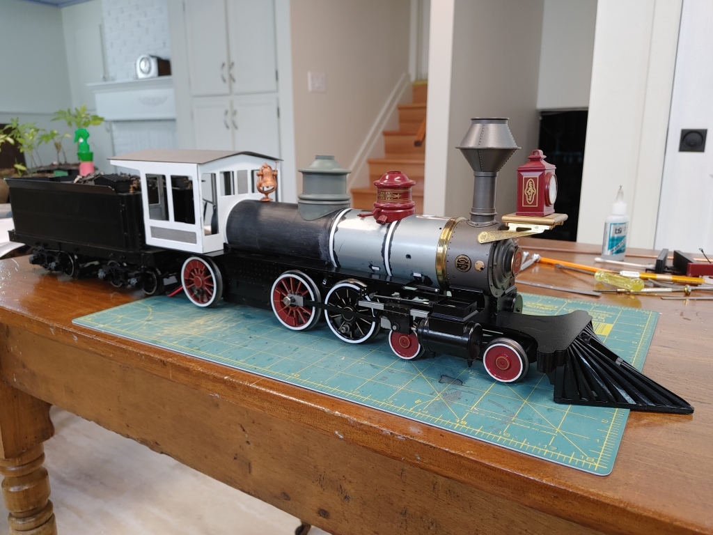
Next? Well once the drivers come in I will finish the bottom end, until then I will continue working on the backhead and get started on the boiler again.
Mike
